Design
Early-on we decided to go with a crane with a rotating boom as we thought this would be the most efficient and practical way of transporting the load.
However to achieve this the length of the boom would need to be at-least 2m to transfer the load 4m from the point of lift. We realised that a 2m beam would be too heavy and large to transport.
To overcome this problem we split the beam into two half's of 1.1m and 1.2m respectively. These two beams would be joined together using this part:-
Each beams will be connected to the I-beam connector by 5 M16 hex bolts, hence insuring structural stability while solving the problem of making the crane portable.
Another feature of the design is hinged leg joints:-
This part of the design allows the crane to be stable while on uneven terrain by adjusting the height of the feet.
This part will be connected to the feet which will clamp to the floor to give the crane a more rigid feel. The feet will be interchangeable so according to the terrain the correct feet can be used.
Here is what the finished crane looks like:-
Detailed Drawings of Each Part
1.1m Beam
1.2m Beam
Center Console
Feet-Leg Connector
I-Beam Connection
Large Leg
Large Leg Connector
Small Leg
Small Leg Connector
Assembly Drawing with Bill of Materials
 (not sure why the pictures are not click-able e-mail me at razaqa@aston.ac.uk if you require better pictures)
(Asrar)
Manufacture and Fitness for Purpose
After extensive researching and brainstorming with the group meeting we decided to use an I-Beam instead of a solid Block or T-Beam.
Reasons
- An I-Beam is generally used for construction and heavy weight lifting purposes this is because it is more stable and deflects less than the T-beam and has a significant amount of weight less than a Solid Block.
- If the amount of material used to produce a I-Beam is less obviously the amount of material used would be less thus reducing the final cost of the product.
After this decision and extensive research on different materials their densities and Young’s modulus calculations were done to calculate the maximum deflection a beam would be able to withstand and the amount our beam would deflect under the maximum load specified. These values came up to be at about 9.28*10^-3m the maximum deflection and 4.2*10^-3m which was the deflection the I-beam would have under the maximum load. This proved that the choice of material, which was carbon steel and length is appropriate so the beam will not fail under maximum conditions.
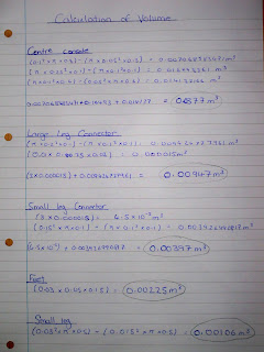
Calculations were also done to calculate the maximum compression on the centre part which came up to about 960KN and then we did some calculations to calculate the compression which it will undergo under the maximum load. We added another 4000Kg in the calculation just to be sure. So the end result was that the maximum compressive force that the centre piece made up of aluminium alloy can withstand is 960KN and the compressive force with 5000Kg would be 50KN which is considerably less than the earlier value and this is under much more weight than the required amount. So this proves that the material used in the centre part is appropriate and it will not fail under maximum conditions.
Finance | Component | Mass | Material | Quantity | Cost |
| Hand Winch |
|
| 1 | £90.95 |
| Pulley |
|
| 1 | £7.64 |
| Wire Rope |
|
| 1 | £32.90 |
| M8 Bolts |
|
| 100 | £5.61 |
| M8 Nuts |
|
| 100 | £2.21 |
| M8 Washers |
|
| 100 | £0.90 |
| M16 Bolts |
|
| 50 | £17.99 |
| M16 Nuts |
|
| 100 | £12.95 |
| M16 Washers |
|
| 100 | £4.87 |
| Boom | 117Kg | Carbon steel | 1 | £52.61 |
| Centre console | 98.018Kg | Aluminium | 1 | £148.28 |
| Large leg connector | 24.621Kg | Aluminium | 1 | £37.25 |
| Small leg connector | 10.327Kg | Aluminium | 1 | £15.62 |
| Feet | 5.85Kg | Aluminium | 3 | £26.55 |
| Small leg | 2.757Kg | Aluminium | 3 | £12.51 |
| Large leg | 3.848Kg | Aluminium | 3 | £17.46 |
| I-Beam connection | 2.104Kg | Carbon steel | 1 | £0.95 |
The total cost of our crane =
£487.25 (excluding manufacturing and labour costs)
(Daljinder)
Conclusion
We have not as yet received accurate costs from manufactures of the cost of labour and manufacture but many companies have quoted us a price in the region of £300.
This will bring the total cost of the crane to £787.25; we will be looking for a unit retail price of £1000 with a 10% discount for buys over 100 cranes.
We think this is a very competitive price and you can be rest assured the quality of our product will be second to none, we are very proud of the reputation our company has achieved over the years and will not let you down.
We look forward to your reply
(Hani)


 (not sure why the pictures are not click-able e-mail me at razaqa@aston.ac.uk if you require better pictures)


